
First I had connected my TV as an external display for my Raspberry Pi 2 running Windows 10 IoT Core. Since I need the little device for some demos, and I want to take it with me I got a Adafruit 5″ LCD display to connected to the device.
The setup with the display is very easy and just plug and play. Just connect the display to the Raspberry Pi 2 board.

But by default the output of the Raspberry Pi 2 is Full HD and so the display setting is kind of wrong. But you change this by editing the config.txt file from the SD card.
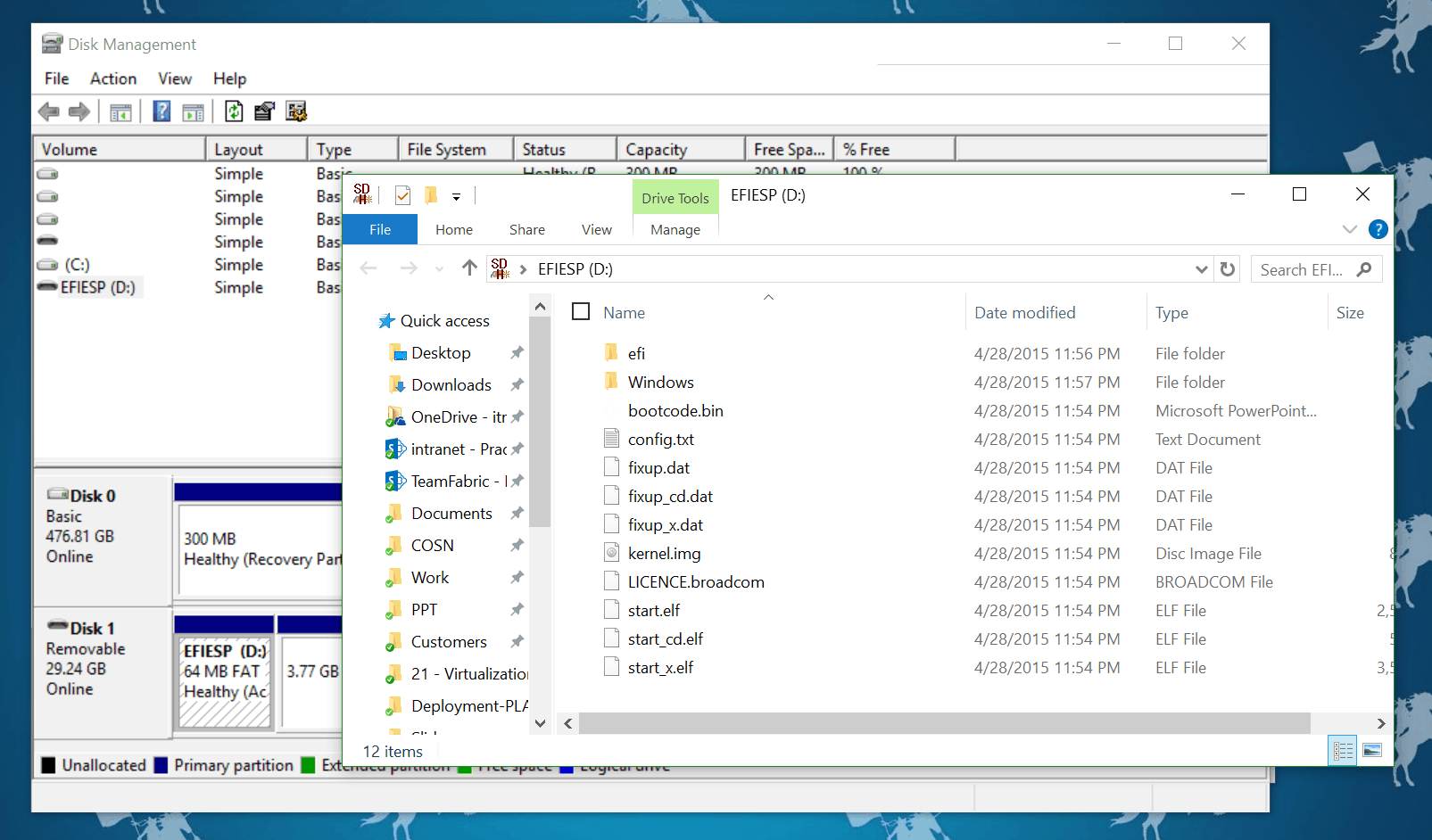
Just open the SD card and add the folloing lines to the config.txt file. (Source)

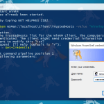
Now you get the perfect outputfor the 800×480 display. If you want to change the settings while the SD card is in the device it self, you can use PowerShell. Remote connect to the Raspberry Pi 2 using Powershell and navigate to C:\EFIESP and check out the config.txt
Get-Content config.txtYou can now set the content of the config.txt file
Set-Content config.txt "
gpu_mem=32 framebuffer_ignore_alpha=1
framebuffer_swap=1
disable_overscan=1
init_uart_clock=16000000
hdmi_group=2
hdmi_mode=1
hdmi_mode=87
hdmi_cvt 800 480 60 6 0 0 0
"
To have the changes active you have to restart the Windows 10 IoT Core device
shutdown /r /t 0
Tags: HDMI, IoT, LDC Display, Microsoft, output, PowerShell, Raspberry Pi, Raspberry Pi 2, Raspberry Pi 2 Windows 10 IoT Core, Windows, Windows 10, Windows 10 IoT, Windows 10 IoT Core Last modified: September 2, 2018


Hallo Thomas,
mir ist gleich beim ersten Bild dieser HDMI Stecker aufgefallen, nur eine Frage: Woher?! Die Bilder von der Seite von adafruit und deinem Display gleichen sich leider nicht! Adafruit hat die Stecker auf der kurzen Seite und dein Display hat diese auf der langen Seite…
gruß
eedroid
Und was ich auch gerne wissen würde… wie verhält es sich mit dem Oberfläche? Besitzt dieser eine Touchoberfläche und funktioniert diese auch? Oder ist der USB Anschluss nur für die Spannungsversorgung?
Gruß
eedroid